Yeah, I could have just renamed it, and no one would ever know. But I'll roll with it. This was my first personal project ever, and what better way to start than by going big: A custom 3D printer!
This post isn't a deep dive into the project development, just an overview of the hurdles I faced along the way.
The Beginning
It was 2015. My first contact with a 3D printer had been six months earlier, during my junior year of college. I was already toying with the idea of building one when the campus lab purchased a Cliever CL1. Despite its flaws, the printer was an incredible piece of tech, and I couldn't wait to try it.
Luckily for me, no one else really knew how to operate it or properly prepare models for printing. Back then, the 3D printing scene in Brazil was just getting started, and learning resources were scarce. I took the opportunity to help other students while getting hands-on experience with the machine. By the end of the year, I was proficient enough to troubleshoot problems and had earned a "free pass" to use it whenever it wasn't busy. This access was critical to the success of my project.
The Mendel90 Plan
I initially chose a Mendel90 design but soon found out that I couldn't simply buy the parts list and start building it, as I couldn't find the parts at all!
And so I officially started working towards my own design of a 3d printer. It all started with these guidelines:
- Keep it cheap: I was a broke college student.
- Locally source the "vitamins": jargon for non-printed parts in the RepRap community.
- Design for small printed parts: I couldn't rely on long, uninterrupted printing sessions.
- Make it unique: Although not a guideline at the start, this quickly became a primary factor in my decision-making.
I started by looking up similar parts to the ones I needed, but that could be easily sourced, and then recreating the Mendel90 on CAD with the new specifications.
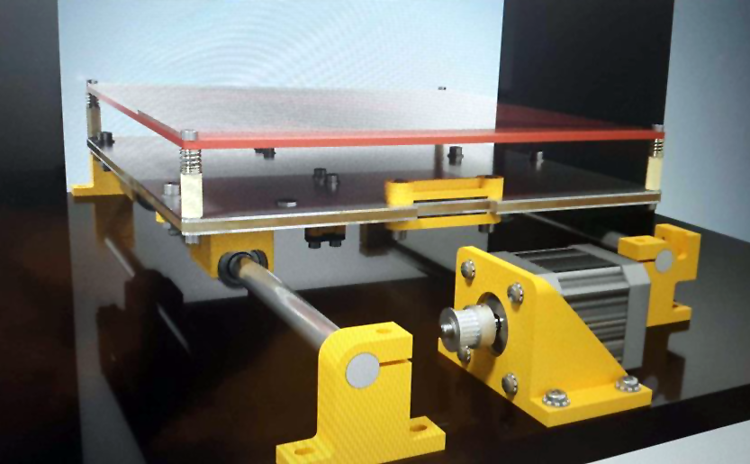
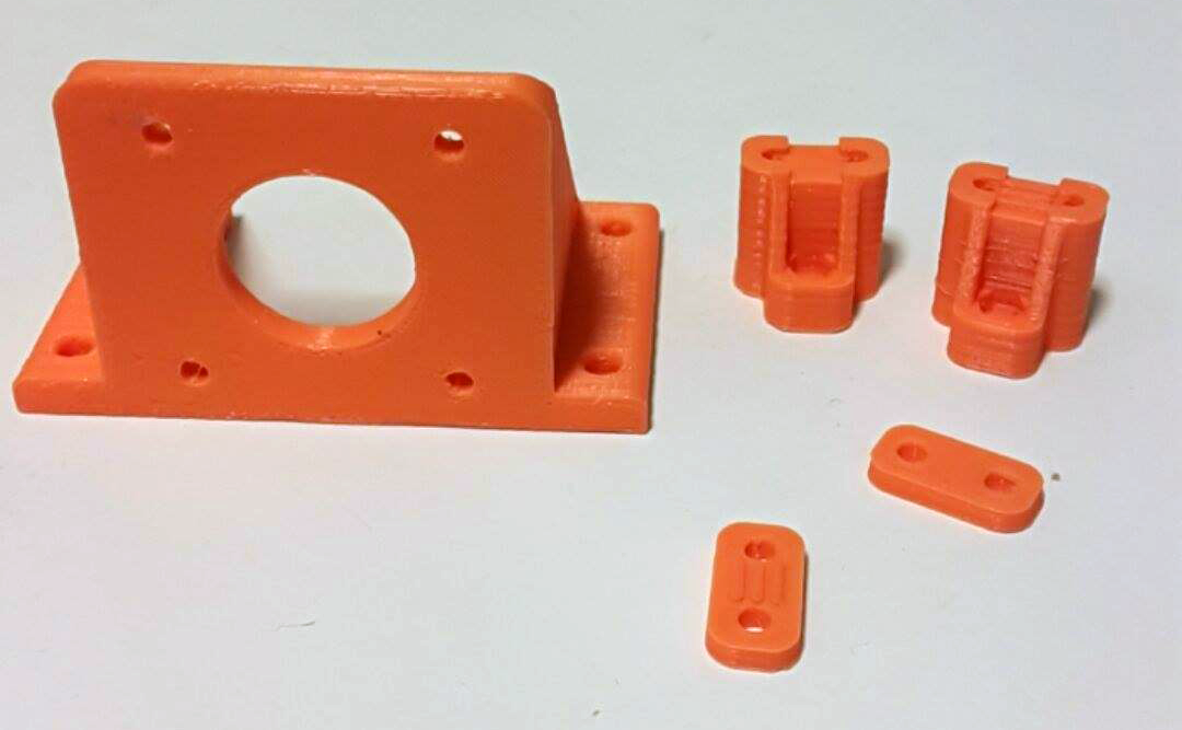
Things started well, but I quickly got ahead of myself when designing the hotend carriage...
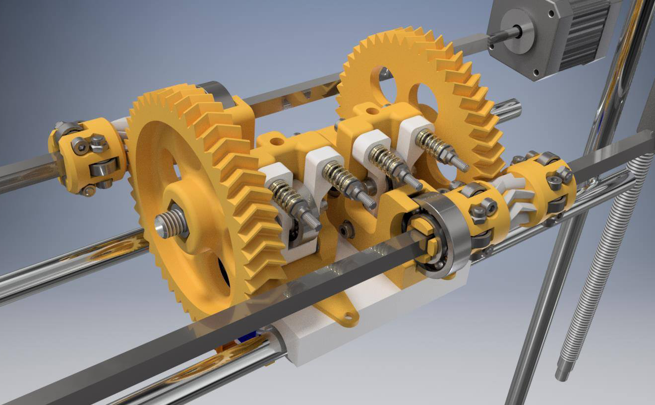
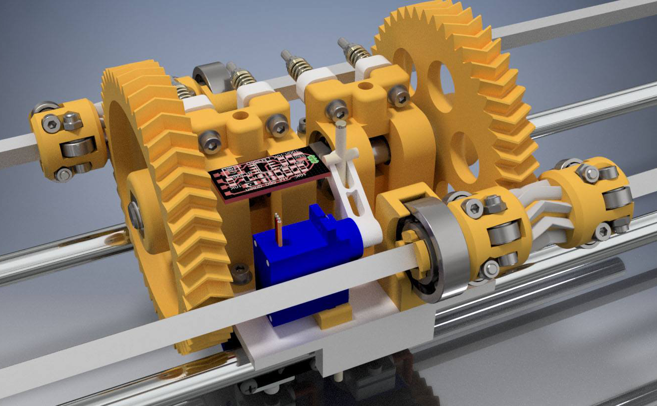
For someone with zero engineering background, the design looked pretty slick! But in retrospect, I broke nearly all my original guidelines:
- Dual extrusion wasn't cheap.
- The parts weren't small.
- The vitamins were getting out of hand.
That said, it sure as hell was unique!
Despite my goal of a low-mass carriage, it became clear I wasn't going to achieve it. Then came an unexpected deadline: my Bachelor's final project was due by the end of the year.
I had a decision to make. My degree in Game Design meant I needed to focus on my final project, and the 3D printer wouldn't help me graduate. To make matters worse, losing access to the campus printer at the end of the year forced my hand.
It was time to scrap everything and start over.
The Tripledoomtopus Inception
This time, I opted for a Rostock design. Delta printers aren't beginner-friendly, but their lower part count and repetitive components gave me a simpler printing process and more time to study. I figured I could tackle calibration and learning after finishing my degree.
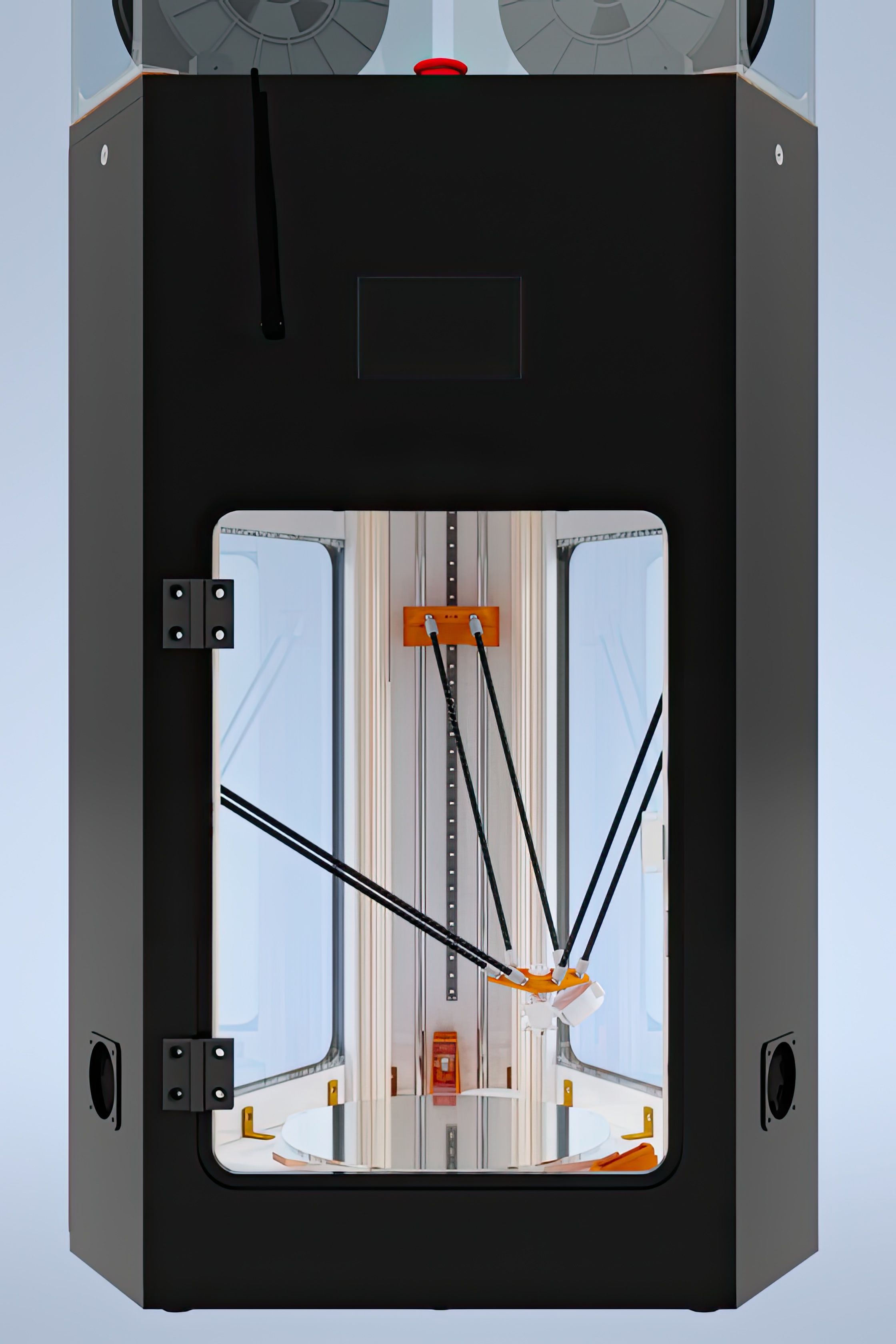
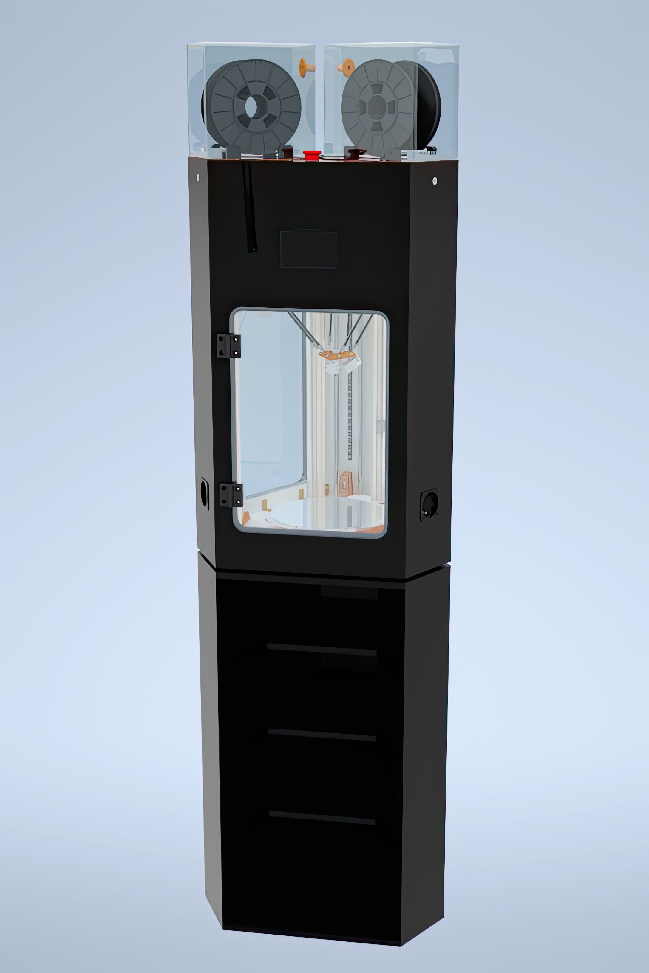

I decided to build it as sturdy as possible since neither weight nor size would be an issue for me at the moment. Also, my experience with the lab's printer suggested its lack of precision stemmed from a floppy bed. So I got inspired by some of the best ideas in the RepRap community, like the Cherry Pi III's clever string retention system. I managed to keep the 3d printed parts count low, but the non-printed ones grew immensely.
For dimensions, I balanced bed size and accuracy:
- 27cm bed diameter.
- 36cm arm length.
- Nearly 30cm print height (with extra travel for even taller prints).
The first step was building the enclosure, which meant learning woodworking...
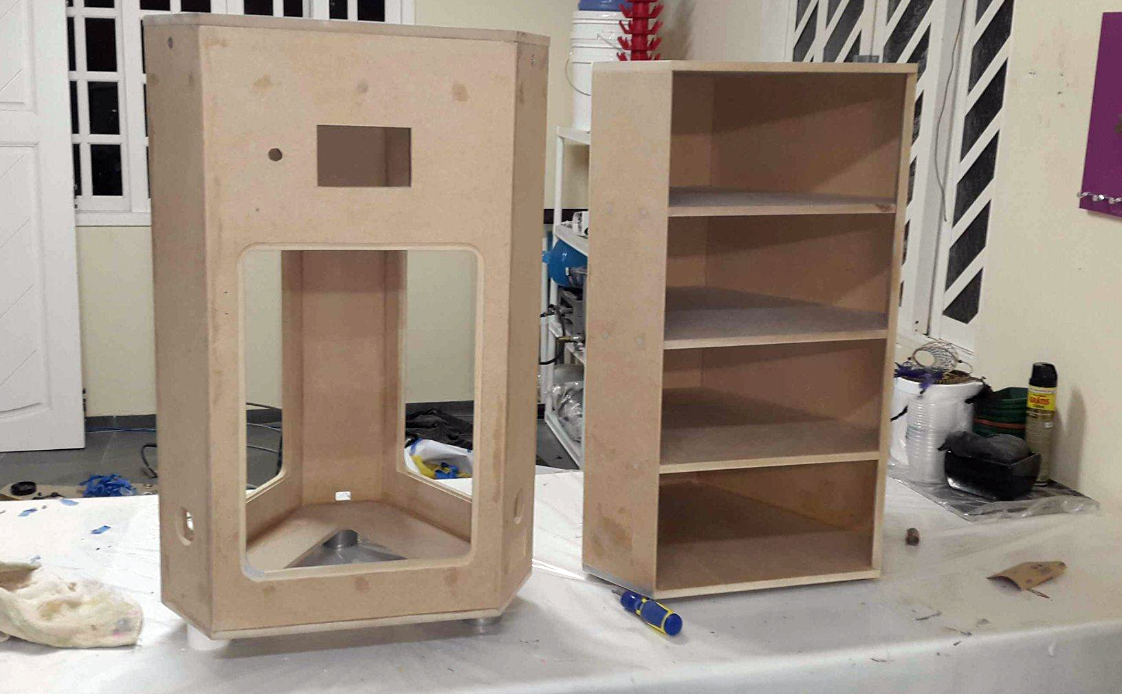
It took weeks of trial and error (and plenty of wasted material), but I learned a lot from my mistakes and tutorials. After some paint, the enclosure was perfect.
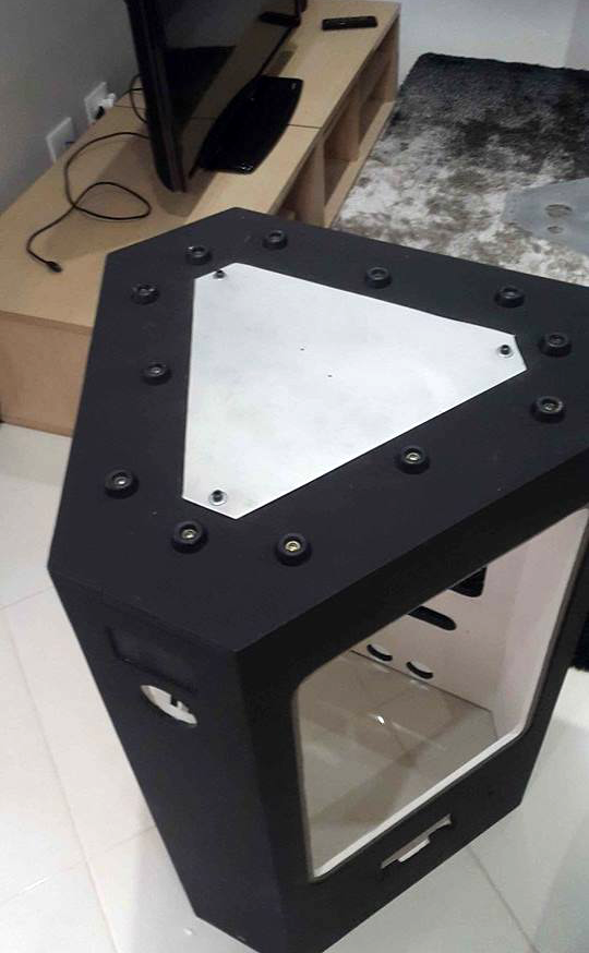
The lower maintenance hatch doubles as the heated bed's SSR heat sink.
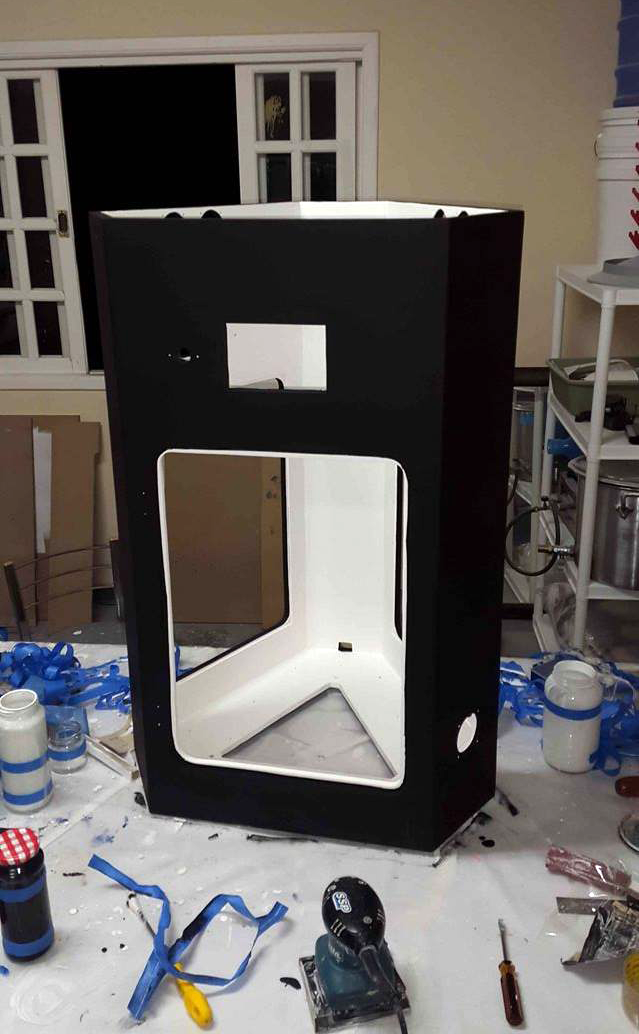
The wooden enclosure was made of 15mm MDF. It wasn't intended to be the just for sturdiness, it also acted as a vibration damper and made the printer cat-proof. Plus, it blended into the living room furniture.
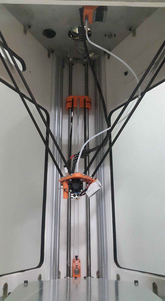
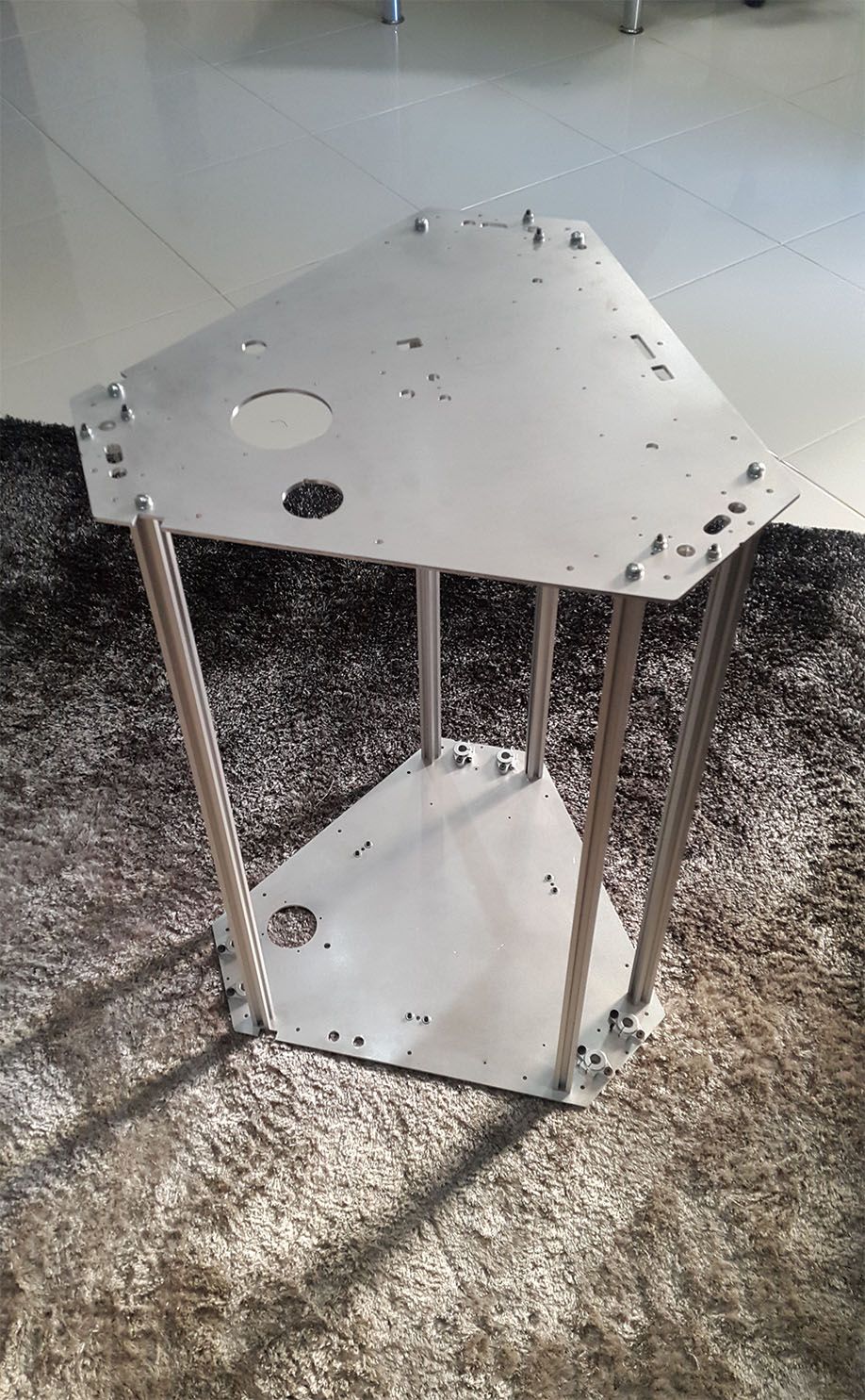
The real strength came from its aluminum skeleton:
- Two milled 4mm aluminum sheets (May sound like the opposite of cheap, but somehow it was).
- Six 12mm linear rods.
- Six aluminum profiles.
This combination made the frame rock-solid, especially when housed in the enclosure.
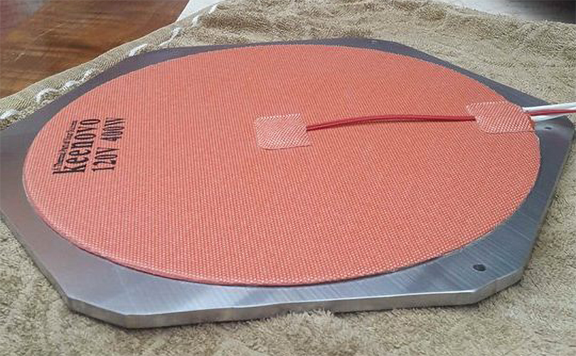
The heated bed was a MIC6 aluminum cast plate with a silicone mat glued underneath for heating. Even after years of use, it has shown no signs of warping, and the heating remains surplisingly even. I've always preferred to print on a 6mm non-tempered round mirror placed over the bed... It's easier to clean, replace, and holds up well at temperatures up to 120°C (maybe more). The only downside? The mounting holes are at a 30-degree angle to the arms, making alignment more challenging than I'd like, but that was a design mistake from my part while milling the aluminum sheets.
By this point, the 3D printer's mechanical parts were ready, and I had an important decision to make about the brains.
Electronics: Buy or DIY?
Until mid-2015, I barely understood circuitry. That changed when I had to learn enough electronics in about three months to build a Bluetooth-enabled wearable PCB for a group project. Pulling that off gave me the confidence, or maybe the overconfidence, to make the wrong choice for this project: DIY it.
I knew a Ramps board wouldn't cut it. While I had an Arduino Mega on hand, a 32-bit controller like the Smoothieboard would be far better for handling the delta movement calculations. I managed to find a used LPC1769 board (Smoothie's microcontroller) for sale, and I thought, how hard could it be to replicate a commercially available controller board?
With that in mind, I started designing a modular system of smaller PCBs:
- LPC1769 board: To house the main controller.
- Mosfet board: For power control.
- Stepper driver board.
- Hall-O Z probe board: (BLTouch wasn't available yet).
- Three Hall-O endstops.
- Mega expansion board: To manage non-essential functions like LED strips, smoke sensors, extra thermistors, and electronics cooling.
- Filament humidity sensor boards.
While the list might seem long, most of the boards were simple. Even the Arduino Mega board was essentially a cleaner protoboard.
Up to this point, I only had experience creating PCBs with the inkjet-and-ironing technique, but this has some limitations with smaller path widths and wasn't going to work this time. I needed something better, and that's when I found out about the UV Light method.
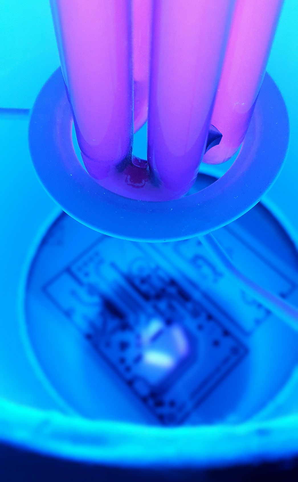
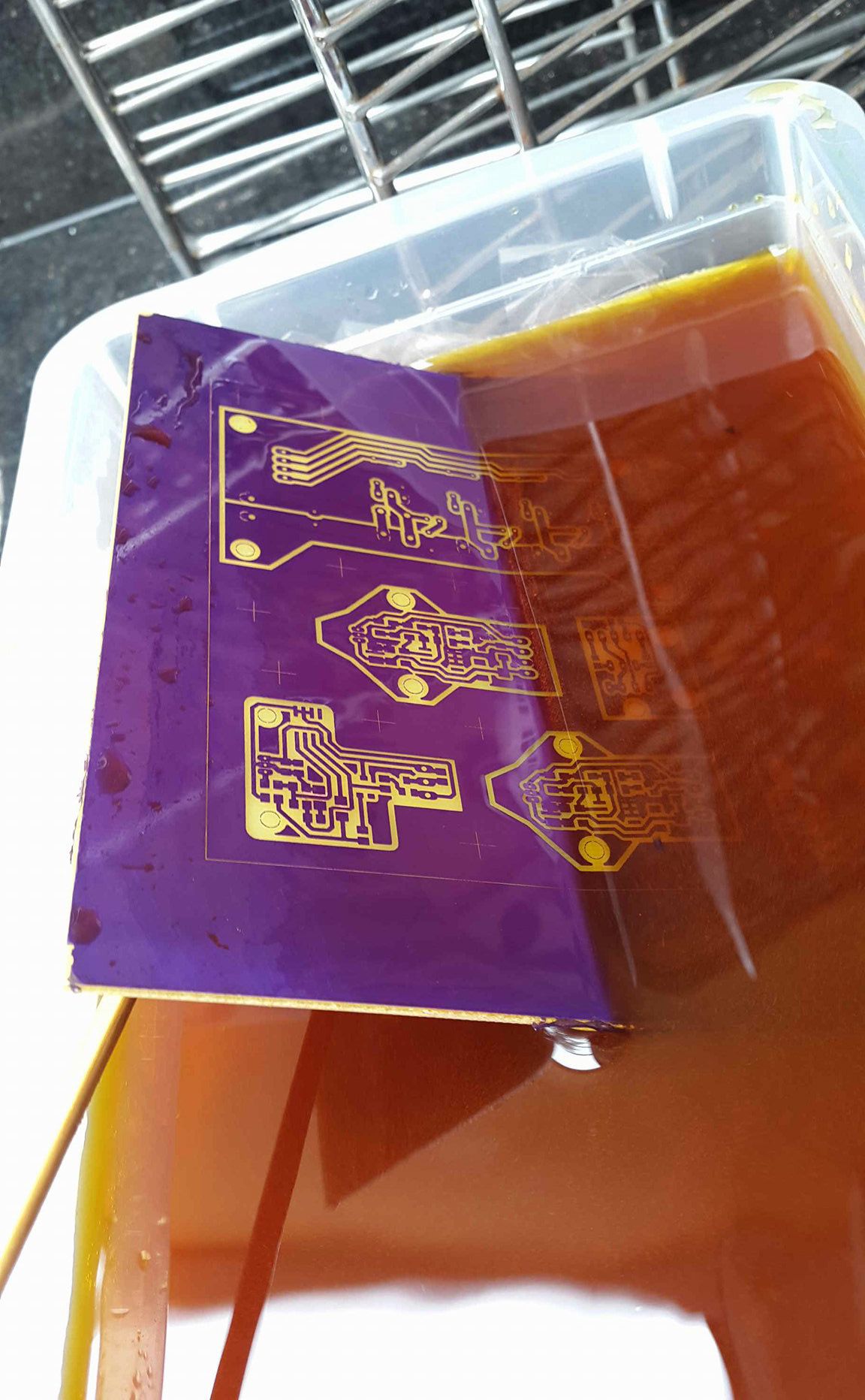
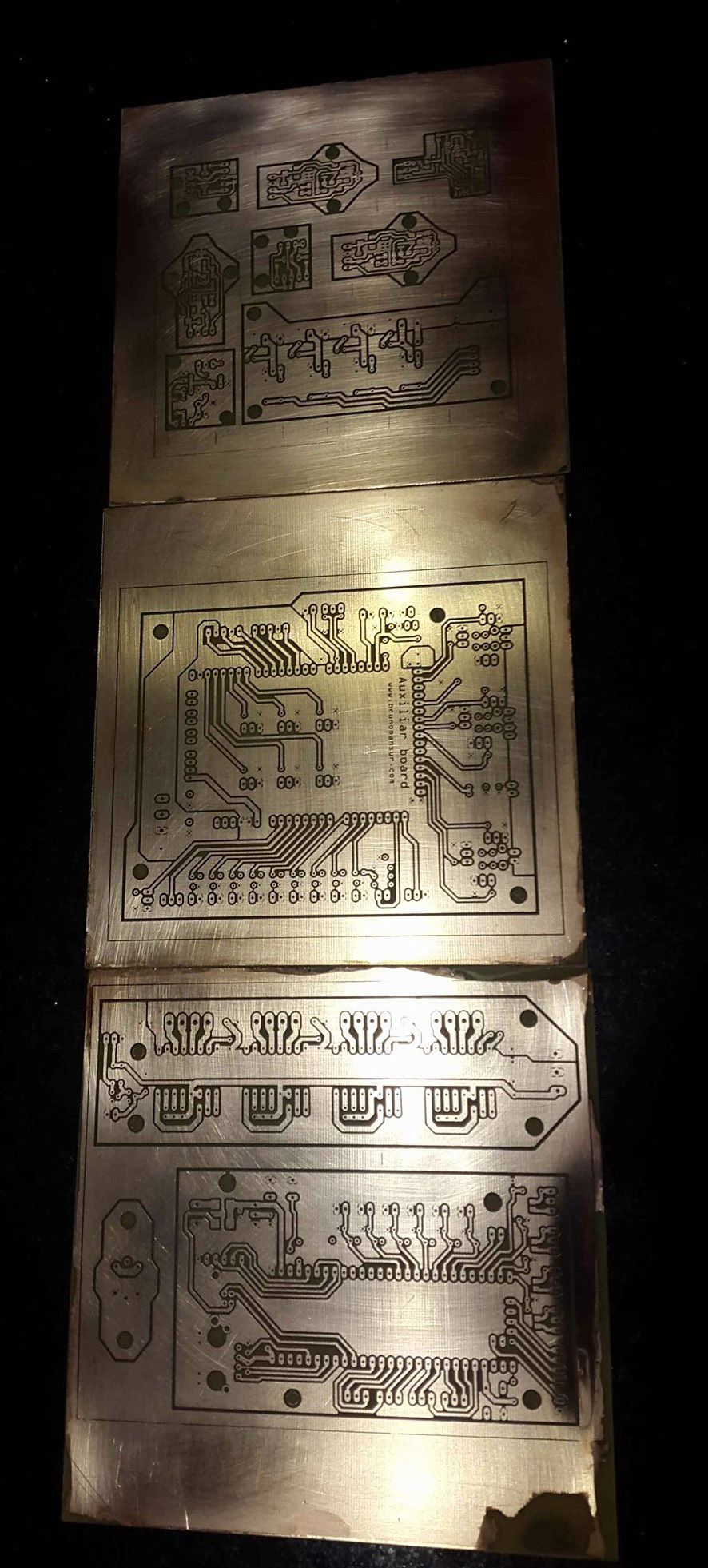
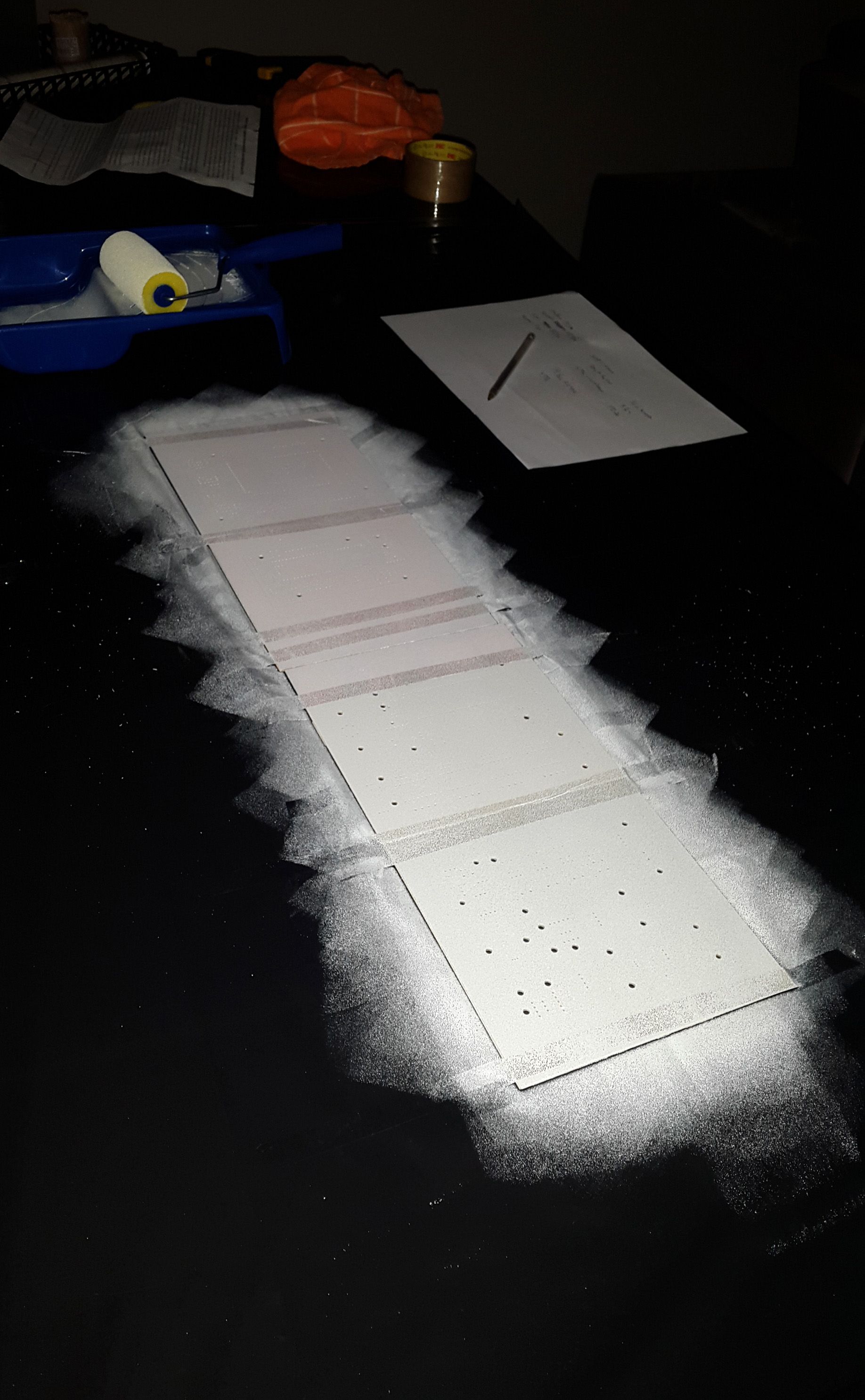
White PCBs are beautiful.
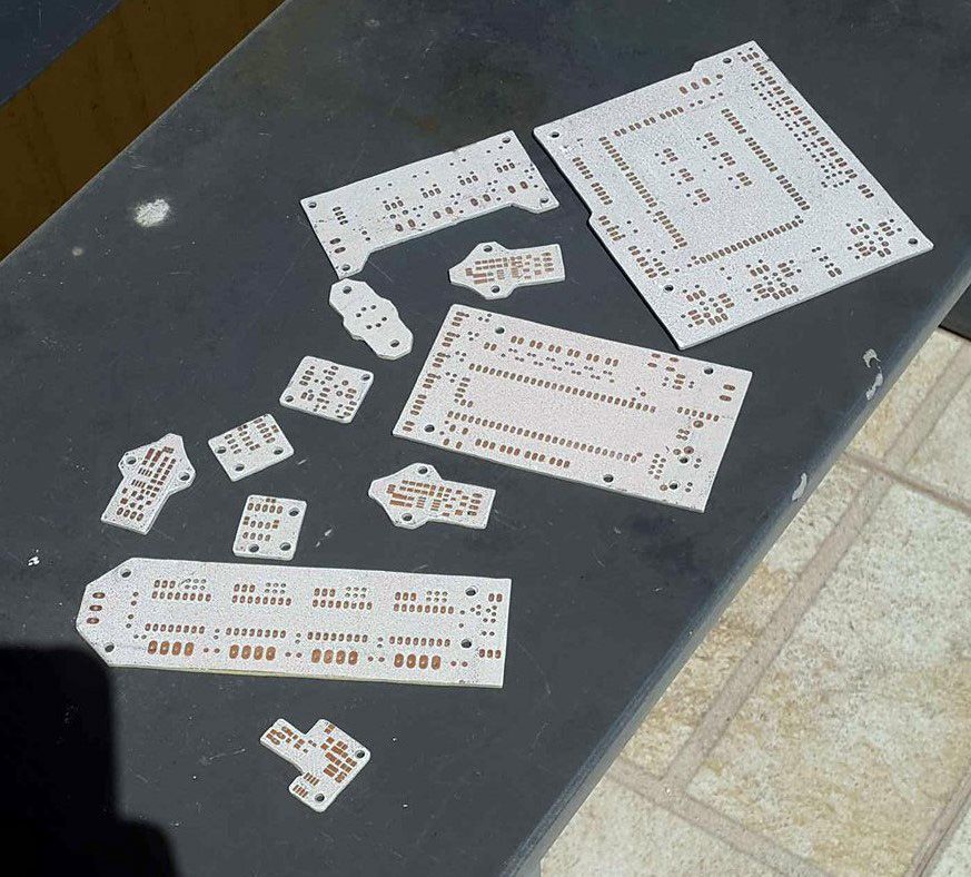
Except for these ones, the mask didn't cure as I imagined.
The process involved printing two inkjet transparencies for each board. The first prepared the board for ferric chloride etching, and the second cured the white solder mask. The results were fantastic! While today it's easy to order custom PCBs online, the hands-on learning experience was worth the extra effort.
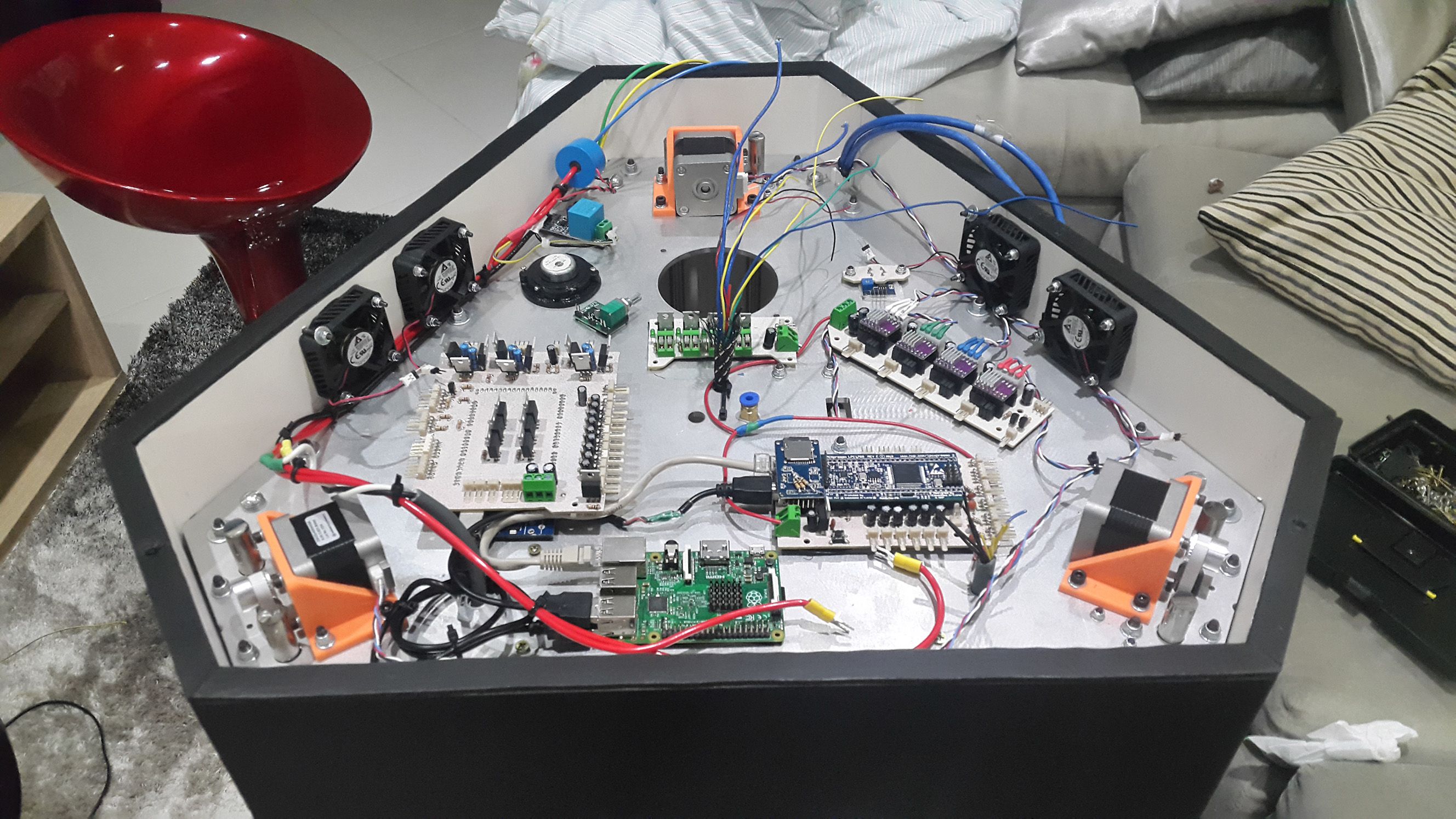
Assembly and Calibration
Installing the circuitry and calibrating the machine took about a week. Honestly, it was easier than I expected, thanks largely to the precision of the CNC-milled aluminum sheets. Every step taken to improve build accuracy saved hours of late-night calibration, especially with a delta printer where diagnosing issues can be a nightmare.
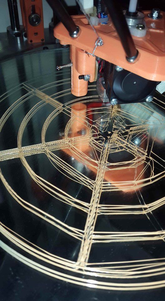
First calibration test

My 3d printer / Campus' 3d printer
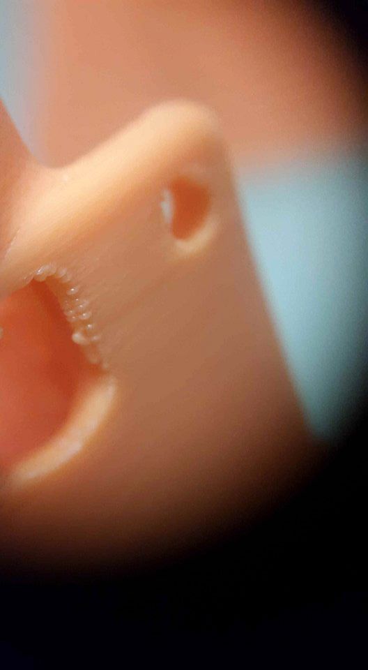
Layer consistency (don't look at the blobs)
By late September 2016, my custom 3D printer, Tripledoomtopus, was fully operational. In fact, the very last part finished printing just an hour before we presented Chickó: A Chicken-Boy Adventure to the evaluation board for my Bachelor's final project.

It was a success!
Reflections
Building this printer was an intense challenge for a beginner in the maker space. But it laid the foundation for my skills in 3D printing, electronics, and problem-solving. It also taught me the value of perseverance, especially in the face of countless mistakes.
Thanks to my friends whose message boxes archived 90% of these pictures—back then, I had a terrible habit of not documenting my work as frequently as I should have.
The verdict? Noisy, but functional.

Update (2021)
Since writing this post in 2020, Tripledoomtopus went through a "2.0" phase. I replaced all the 3D-printed parts with new designs, swapped the DIY Smoothieboard for a Duet 2, and built a modular head. You can read more about it here.