Recently, I bought a few SuperMini boards of the new ESP32-H2, a new SoC with built-in mesh networking features. I didn't have a project for them yet, but I do have a Zigbee hub at home connected to a single IoT device, so anything that could justify keeping the Zigbee Hub, Zigbee2MQTT, and Mosquitto running would be nice.
While looking around for anything that wasn't integrated with Home Assistant yet, I found a Blisslight Skylite 2.0 I got a few years ago. It never saw much use though. It's Bluetooth-only, so I had to pair with it and use its proprietary app to do anything.
Tearing It Down
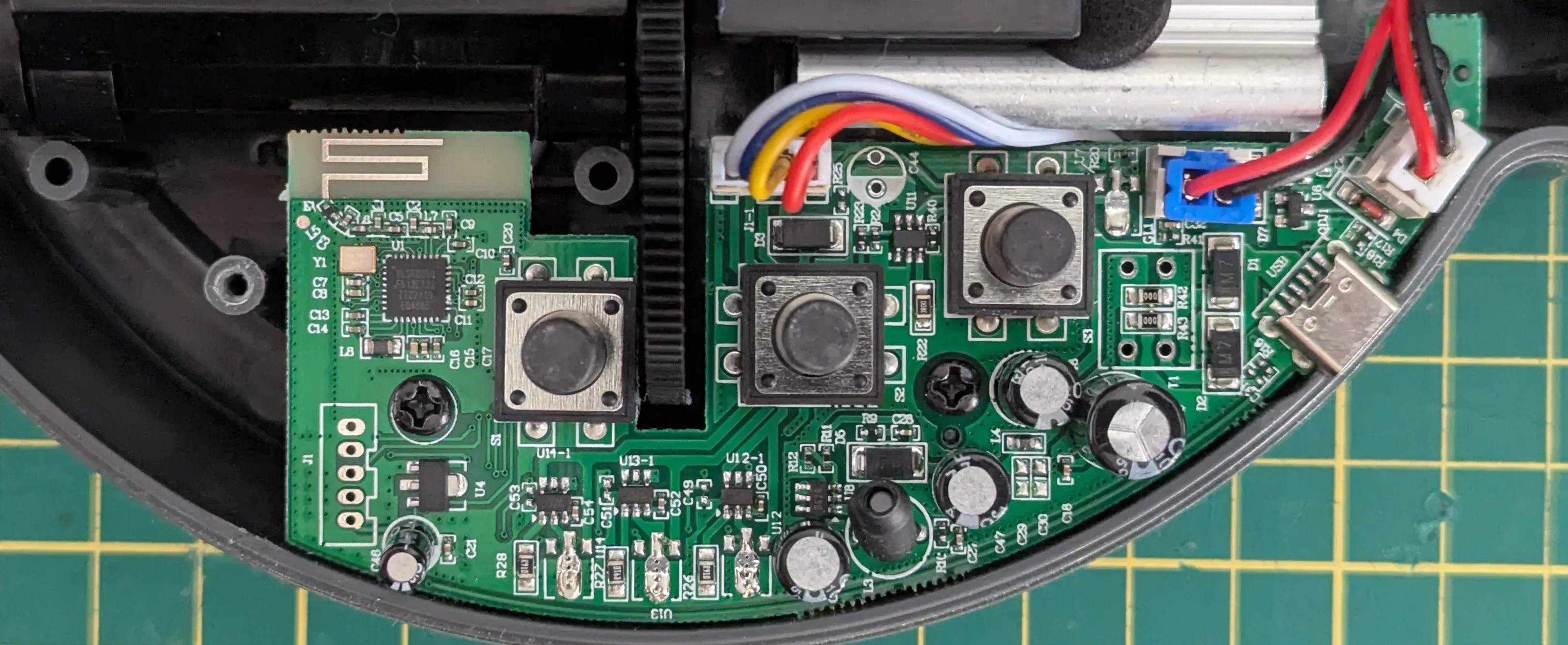
After disassembling it, I found a Telink TLSR8250 Bluetooth SoC controlling the operations, which I'm glad has an easily available datasheet that helped a lot with the light reverse engineering I had to do.
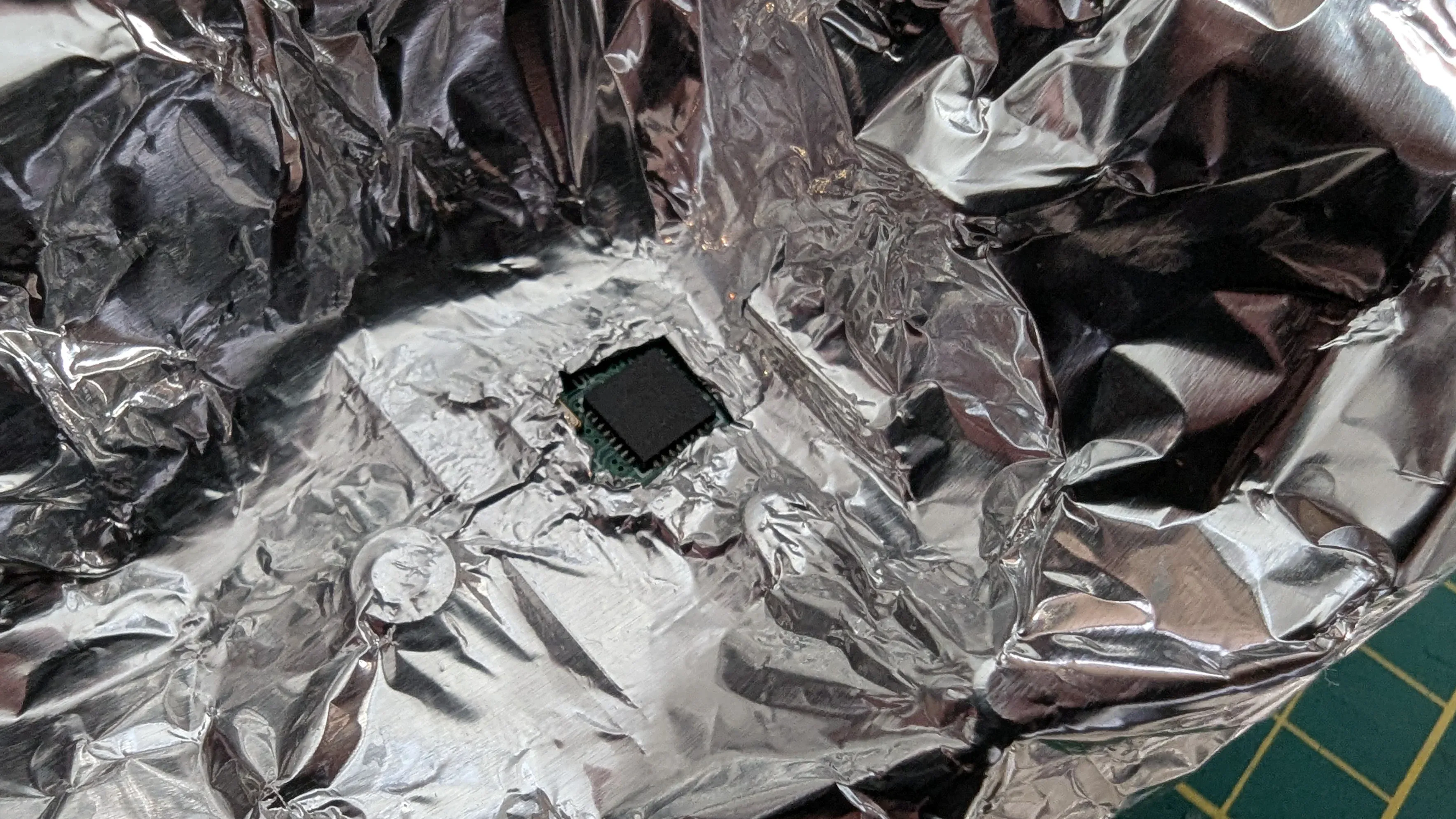
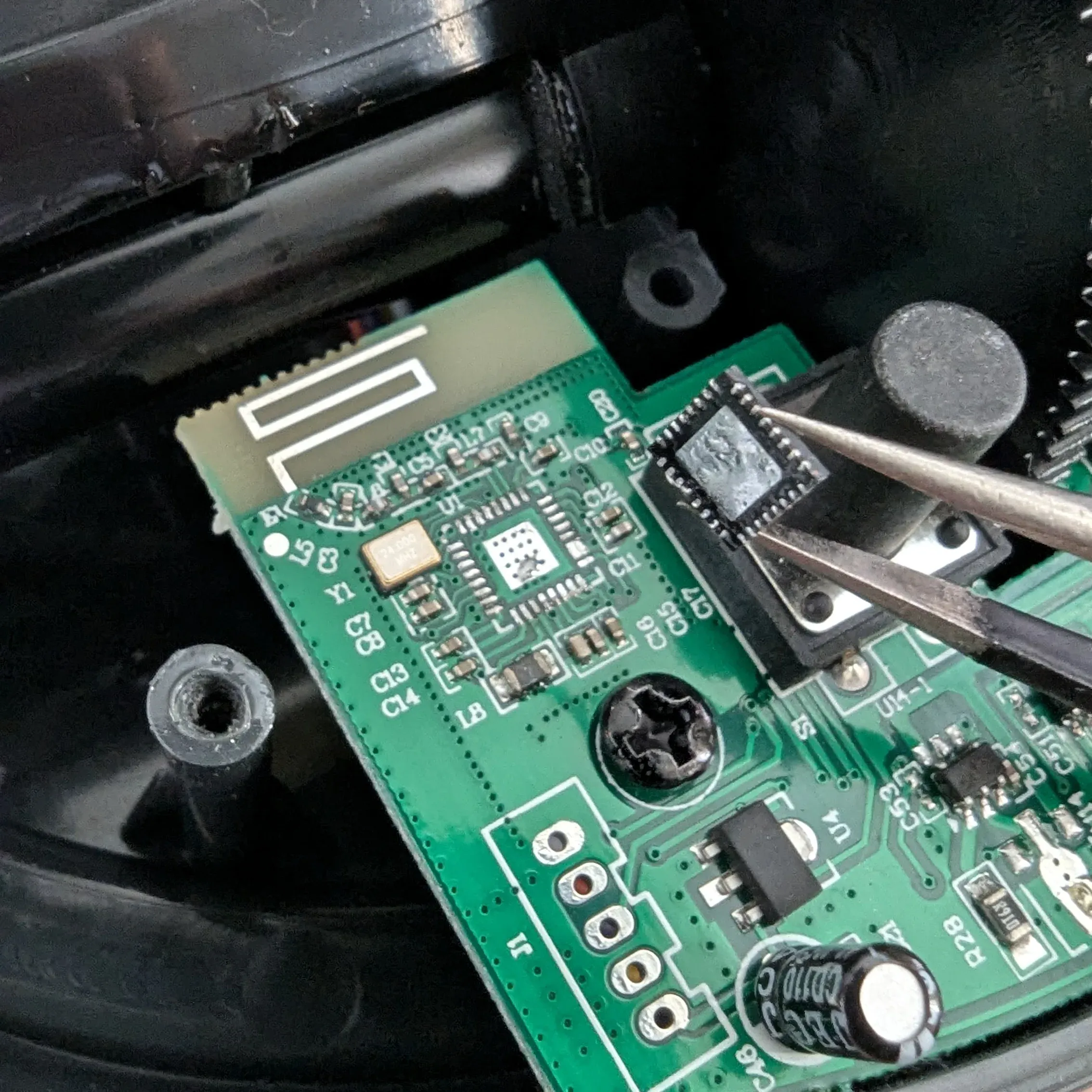
I started by wrapping the board in aluminum foil and opening a cutout where the TLSR8250 is. Used a heat gun to get it out and cleaned up the pads. I didn't care much about doing a reversible change, so I'd rather not have the original SoC interfering with the new signal lines.
Reverse Engineering
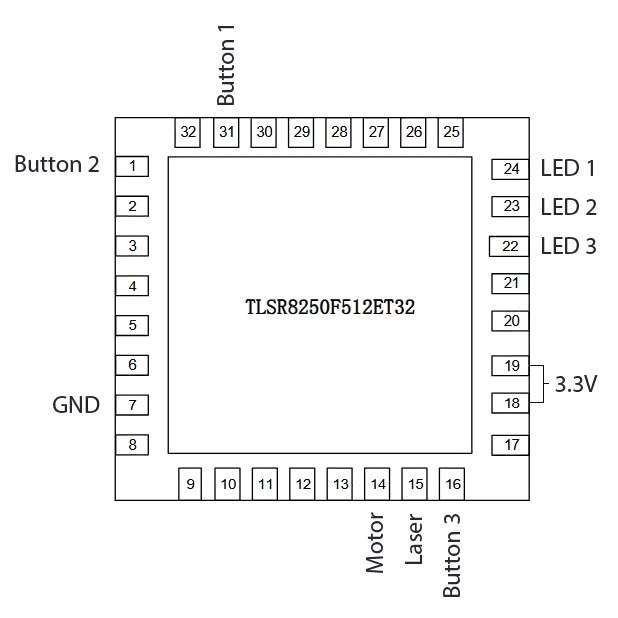
I mapped out which pins were in use by the core functions of the projector: 8 signals, one for each of the three buttons, 3 for the RGB LEDs, one for the laser, and another for the DC motor driver. All running on a 3.3v logic level, so migrating to the ESP32-H2 was going to be straightforward.
Hardware Swap
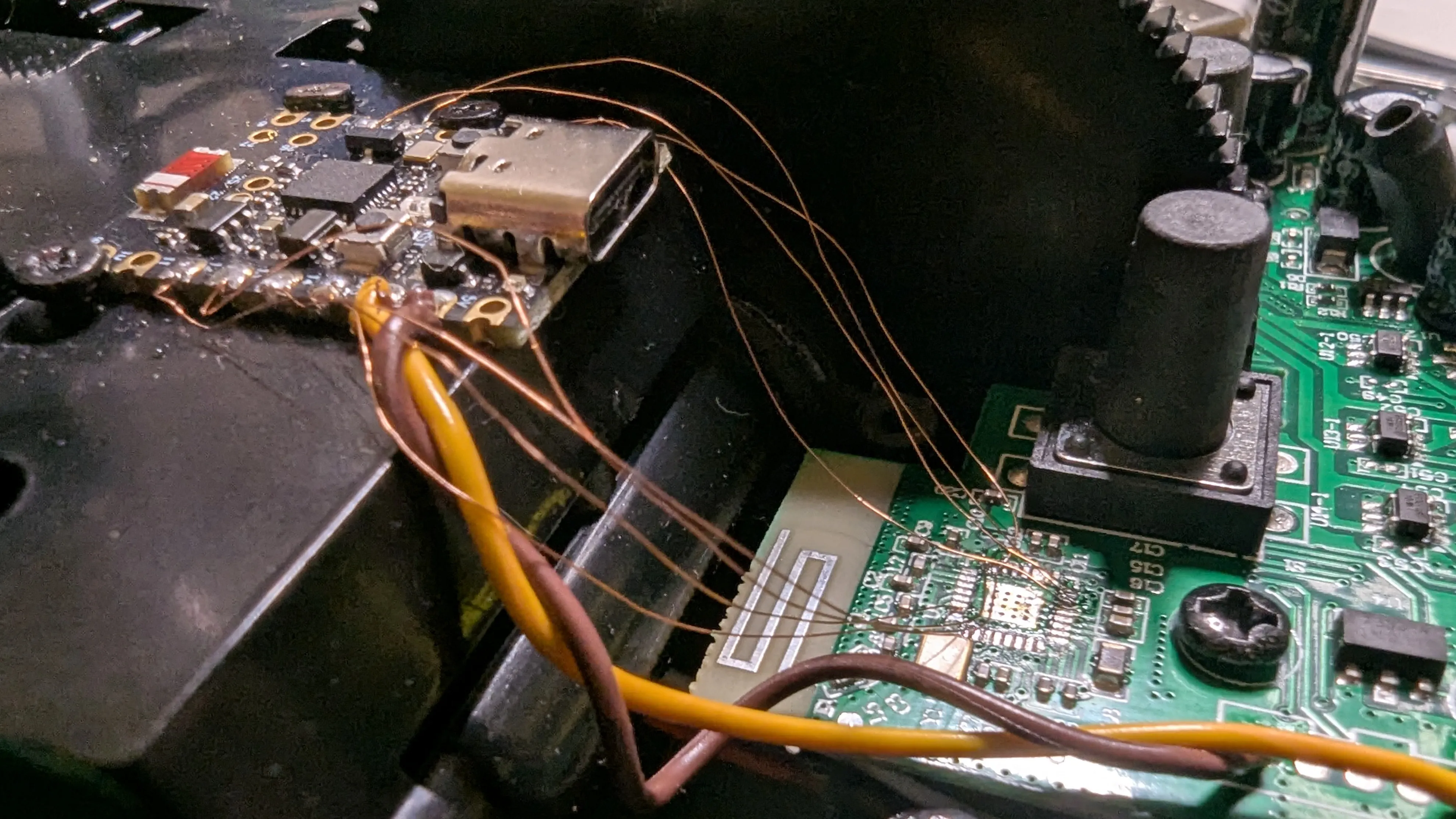
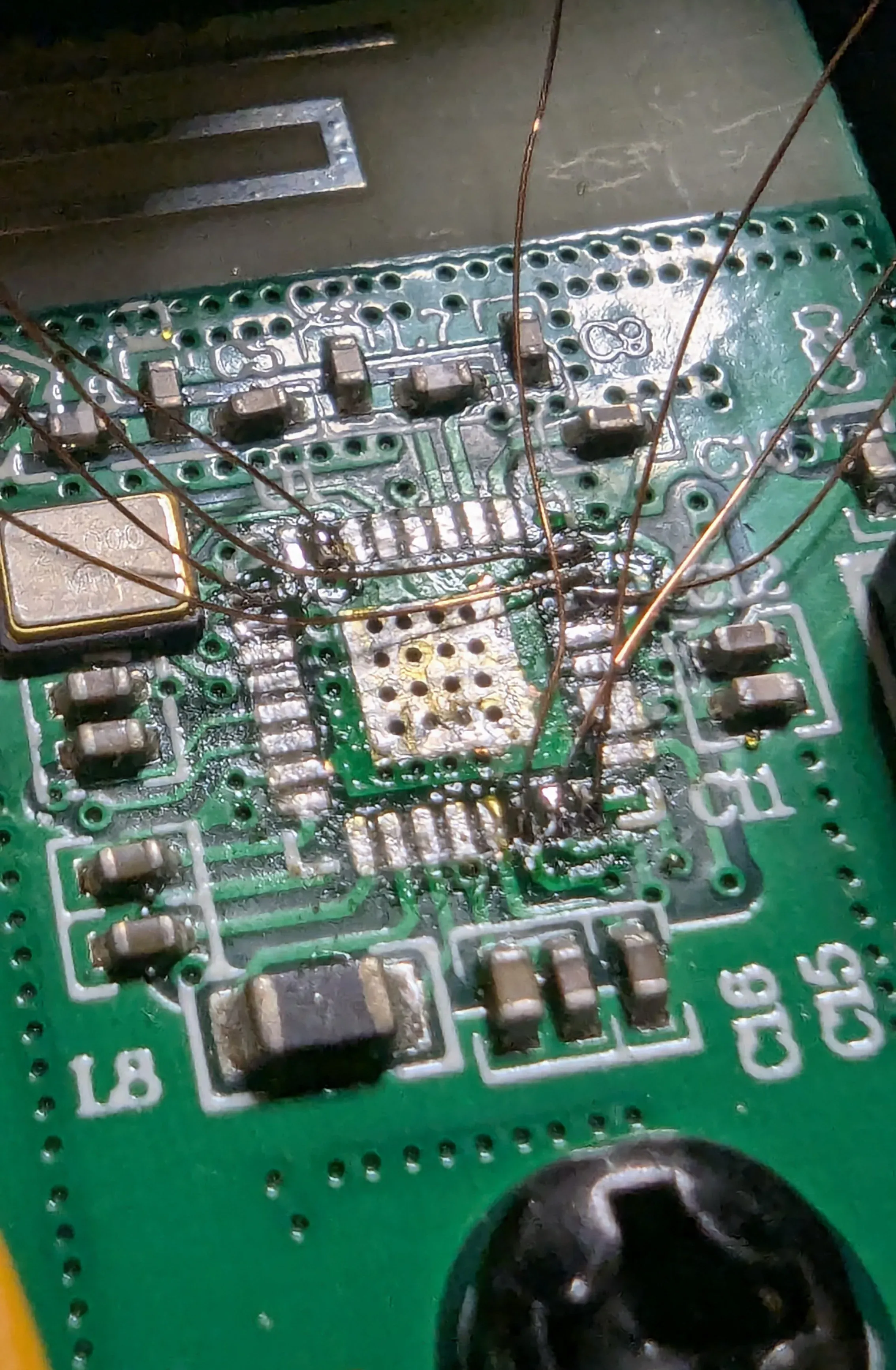
I drilled a few holes in the mechanical/LEDs housing to hold the ESP32-H2 in place (using small screws aligned with the castellated holes on the PCB), so I had a good starting point for connecting the exposed pads to the new controller. Since I had to use a very thin copper wire, I didn't want to risk just leaving it hanging inside the case.
The pads were pretty small and packed together (32-pin TQFN form factor after all), so I thought about connecting the ESP32 to test pads closer to the buttons and LEDs, but I had just bought some extra-thin soldering iron tips and decided to go for it and solder a 0.1mm enameled copper wire directly to the pads. I was half expecting to botch it, but it worked.
Le Firmware
With that done, I still had to write the code to allow control using Zigbee. Luckily, I found that arduino-esp32 had tons of Zigbee examples, so I had a good base to get started.
HSL to RGB Quirk
The first hurdle I found was getting the light to work at full intensity. I noticed that when setting the aurora color via Zigbee2MQTT, the overall light output was pretty low. When selecting the exact middle of the color wheel, the light intensity was about half of what I could achieve by setting them manually to max. This might be a quirk of the color conversion implementation, but I didn't give it too much thought.
My workaround was to use the brightest color as the ceiling of the color range when mapping to 10-bit (PWM resolution I'm using):
normalized light level
void setLight(bool state, uint8_t red, uint8_t green, uint8_t blue, uint8_t level)
{
  if (!state || (red == 0 && green == 0 && blue == 0))
  {
    led_r_target = 0;
    led_g_target = 0;
    led_b_target = 0;
    return;
  }
  uint8_t brightest = red;
  if (blue > brightest) brightest = blue;
  if (green > brightest) brightest = green;
  led_r_target = map(red, 0, brightest, 0, 1023) * level / 255;
  led_g_target = map(green, 0, brightest, 0, 1023) * level / 255;
  led_b_target = map(blue, 0, brightest, 0, 1023) * level / 255;
}
It solved my problem, but the default Zigbee colorloop effect stopped working, so I assume it worked the way it did by design. Anyway, I'm going to implement an animation effect later.
Transitions
You may have noticed that I'm saving the calculated PWM to a variable instead of writing to GPIO. I put a LED updater function in the loop() call to refresh the light color based on the deltaTime between loops. Since I'm using 10-bit (0-1023), it takes approximately 1 second to go from off to full brightness, which looks less jarring.
At this point, I had all the features that the Skylite 2.0 also had out of the box. But how could I improve it further?
Aurora-like animation
Next, I applied a sine wave effect to each color with a 120-degree offset. It worked but looked a bit too artificial. So I tweaked it so each color had a different frequency, and the phases drifted at different rates over time. Finally, the sine wave modulated from 20% to 100% of the target intensity, since turning a color off completely looked a bit lame.
The animation speed varies from 2 minutes to 5 seconds, and can be configured by a Zigbee endpoint of type ZigbeeAnalog.
animation logic
if (animationSpeed > 0.0f)
{
  float logScale = log10f(animationSpeed);
  float scaleFactor = logScale / 2.0f;
  float frequency = MIN_FREQ * pow(FREQ_RATIO, scaleFactor);

  float freqR = frequency * 0.8f;
  float freqG = frequency;
  float freqB = frequency * 1.3f;

  angleR += deltaTime * freqR;
  angleG += deltaTime * freqG;
  angleB += deltaTime * freqB;
  phaseR += deltaTime * 0.000005f;
  phaseG += deltaTime * 0.00002f;
  phaseB += deltaTime * 0.00006f;

  // Sine modulation from 20% to 100% of target.
  float rWave = (sinf(angleR + phaseR) + 1.0f) * 0.4f + 0.2f;
  float gWave = (sinf(angleG + phaseG) + 1.0f) * 0.4f + 0.2f;
  float bWave = (sinf(angleB + phaseB) + 1.0f) * 0.4f + 0.2f;

  adjusted_r = constrain((uint16_t)(led_r_target * rWave + 0.5f), 0, 1023);
  adjusted_g = constrain((uint16_t)(led_g_target * gWave + 0.5f), 0, 1023);
  adjusted_b = constrain((uint16_t)(led_b_target * bWave + 0.5f), 0, 1023);
}
Zigbee2MQTT Integration
This isn't related to the ESP32 firmware but to Zigbee2MQTT itself. I had to write the following converter and place it on /app/data/external_converters/, to properly map the endpoints and display them in Home Assistant:
skylight-converter.js
import * as m from 'zigbee-herdsman-converters/lib/modernExtend';

export default {
    zigbeeModel: ['SkyLite'],
    model: 'SkyLite',
    vendor: 'BrunoTuma',
    description: 'Zigbified Blisslight Skylite 2.0',
    extend: [
        m.deviceEndpoints({ endpoints: { light: 10, laser: 11, motor: 12, effect: 13 } }),
        m.light({ powerOnBehavior: false, color: {modes:["xy"]}, endpointNames: ["light"], effect: false }),
        m.light({ powerOnBehavior: false, color: false, endpointNames: ["laser"], effect: false }),
        m.numeric({ endpointNames: ["motor"], name: "rotation", unit: "%", valueMin: 0, valueMax: 100, cluster: "genAnalogOutput", attribute: "presentValue" }),
        m.numeric({ endpointNames: ["effect"], name: "colorloop", unit: "%", valueMin: 0, valueMax: 100, cluster: "genAnalogOutput", attribute: "presentValue" })
    ],
    meta: { "multiEndpoint": true },
};
Still on the To-Do List
Finally, there are two things I'm still considering doing:
Router Mode
I couldn't get the ESP32-H2 to act as a Zigbee Router instead of an End Device. That would allow it to also extend the range of my IoT network. I tried following the example provided by the Zigbee library, but Zigbee2MQTT was failing to interview the device with the following message:
Interview failed because can not get node descriptor.
I won't need this feature anytime soon, so I'm not troubleshooting that for now.
Integrate the laser and motor to the animation cycle
One last thing I want to experiment with is linking the rotation speed of the wavy glass to the sum of the three colors' brightness, or something like that. Also, maybe implementing a perlin noise generator for the laser that projects the stars.
Wrapping up
I'm digging the new animation effect, but... Now that I can include the Skylite in my automations, maybe the next step would be to automatically turn it on when the Kp-index gets above a certain threshold in my location? 🌌
The full code can be found on github.com/b-tuma/ZigbeeSkylite.
